IDEX/IQEX Parallel Printing
Important
NEW FEATURE: IDEX/IQEX parallel printing
Available in: Nightly builds or Releases greater than 2.4.2.
Printers with independent carriages can print several copies of a part at the same time, one per carriage. OrcaSlicer slices the part once, for tool T0, shows where every carriage will print on the plate, keeps parts out of the areas where the carriages could collide, and tells the firmware which mode to run.
This guide covers how parallel printing works, how to set a printer up, and how to use it day to day. The individual settings are described in IDEX/IQEX Configuration.
How parallel printing works
In a parallel mode, the bed is split into one zone per active carriage. A Span partner shares T0's zone, and in a Span mode the other gantry's carriages share one zone when they have the same role. T0 prints in its zone, the primary zone, from the toolpaths OrcaSlicer slices. Every other active carriage repeats those moves in its own zone, driven by the firmware:
- A Copy carriage prints the same part, moving the same way as T0.
- A Mirror carriage prints a mirror image, reflected across the boundary with T0's zone: in X for a carriage on T0's gantry, in Y for a carriage on the other gantry.
Each plate has its own mode, so one project can mix normal plates, printed one tool at a time, with copy or mirror plates. The modes themselves are defined once, in the printer settings.
Supported layouts
- One gantry with two to four carriages, such as a classic IDEX.
- Two gantries with one carriage each, a dual-gantry IDEX: two independent XY systems over one bed.
- Two gantries with two carriages each, an IQEX, printing up to four parts at once.
On a dual-gantry printer with two carriages per gantry, T0 and a Span partner can also print a part in several colors while the other gantry copies or mirrors it. For firmware that moves each carriage into its zone with its own offset, see Firmware-managed zones.
Setting up a printer
- Set Extruders on the Multimaterial page to the number of toolheads, or to the number of filament slots if an MMU feeds a toolhead (see MMU and AFC).
- In Advanced mode, enable IDEX/IQEX Printer further down the same page.
- Describe the hardware: Gantry Count, Tools per Gantry and Tool 0 Position.
- Measure the carriages and enter Nozzle Clearance X (and Nozzle Clearance Y on a two-gantry printer). They set the strips where parts cannot be placed, so err on the generous side.
- In the Modes grid, add the parallel modes your printer supports, giving each tool a role and each mode the G-code that tells the firmware about it (see Firmware).
Firmware
OrcaSlicer does not move the other carriages itself. It writes the active mode's G-code just before the machine start G-code, and the firmware does the rest, so the firmware must already have copy and mirror modes. In a parallel mode, OrcaSlicer also leaves out the tool change to T0 at the start of the print, so the mode G-code or the start G-code has to select it.
That G-code runs before the start G-code homes the printer. If your firmware needs a homed printer to switch modes, or resets the mode when it homes, as Klipper does, have the mode G-code only record the mode, and switch into it in the start G-code after homing. The start G-code can also read the active mode from the imex_mode variable.
The firmware also decides where each carriage starts, and that has to match the zones OrcaSlicer draws. A copy carriage stays as far from T0 as its zone is from T0's zone, which is half the bed with two carriages, and a mirror carriage is at the far edge when T0 is at the near one. If the firmware places the carriages differently, the copies will not print where the plate shows them.
The mode is set once, at the start of the print. Switching modes partway through a print is not supported.
MMU and AFC
A printer can have more filaments than toolheads, for example four lanes of an AFC unit feeding T0 plus one filament on each of the other toolheads. The printer profile then lists one extruder per filament slot, and physical_extruder_map maps each slot to its toolhead, numbered from 0, so that pressure advance and temperatures go to the right toolhead:
Here the first four slots all feed toolhead 0, and the last three feed toolheads 1 to 3. The map needs exactly one entry per extruder; otherwise OrcaSlicer ignores it and treats every slot as its own toolhead. There is no setting for it in the printer settings, so add it, with OrcaSlicer closed, to the printer preset's JSON file in your configuration folder, or use a vendor profile that includes it. Printers without an MMU need no map.
Firmware-managed zones
If the firmware moves each carriage into its zone from X0 Y0 with its own offset, as a RepRapFirmware duplication tool can, enable Firmware-managed zones. In parallel modes, the G-code is then written with the middle of T0's zone at X0 Y0. The preview shows the shifted G-code, and ghost copies are not drawn.
Working with parallel printing
Choosing a mode for a plate
When the printer is set up, each plate has a mode icon next to its other plate icons:
- Left-click steps through the printer's modes.
- Right-click opens a menu of all modes.
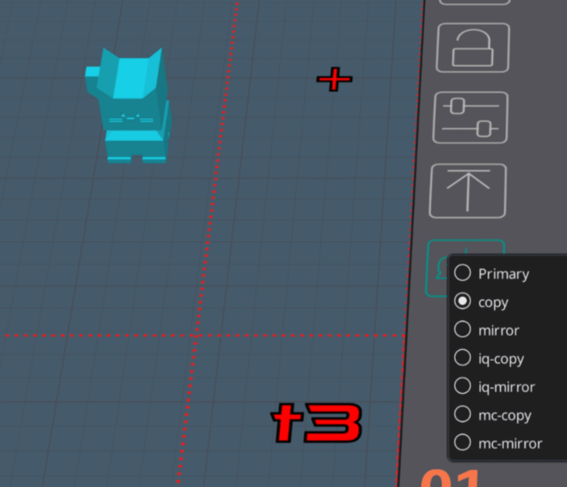
New plates start in Primary, the normal mode, where any tool can print but only one at a time. The mode is saved with the project, and changing it can be undone. A warning badge on the icon marks a plate that uses more filaments than its mode can print, or a mixed filament; see Multi-color printing.
Placing parts
In a parallel mode, the plate shows each carriage's zone. The primary zone is shown normally and the other zones are tinted by role. Place parts only in the primary zone; the other carriages print them in their own zones automatically.
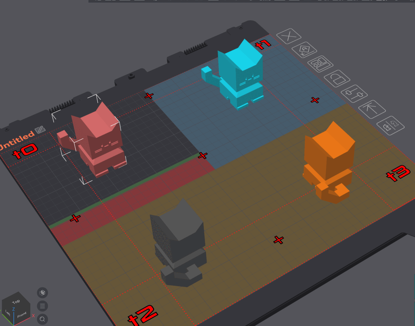
- Next to a Mirror zone, a clearance strip marks where the carriages could collide. Parts and the prime tower must stay outside the primary zone's strips and inside the zone, or the plate will not slice.
- Arranging a plate keeps its parts inside the primary zone and out of the clearance strips.
- An optional Safety Margin draws an extra band beside each strip as a reminder only; parts in it still slice.
Zones are sized from the active carriages only, so a carriage that is inactive in a mode gives its share of the bed to its neighbors.
Ghost copies
Each Copy and Mirror carriage shows a semi-transparent ghost of the parts in its zone, mirrored for Mirror carriages, and the ghosts follow the parts as you move, rotate or scale them. Hovering a ghost shows which tool and filament it uses. When T0 has a Span partner and both carriages on the other gantry have the same role, that gantry shows a single ghost for the pair, in one filament's color rather than both.
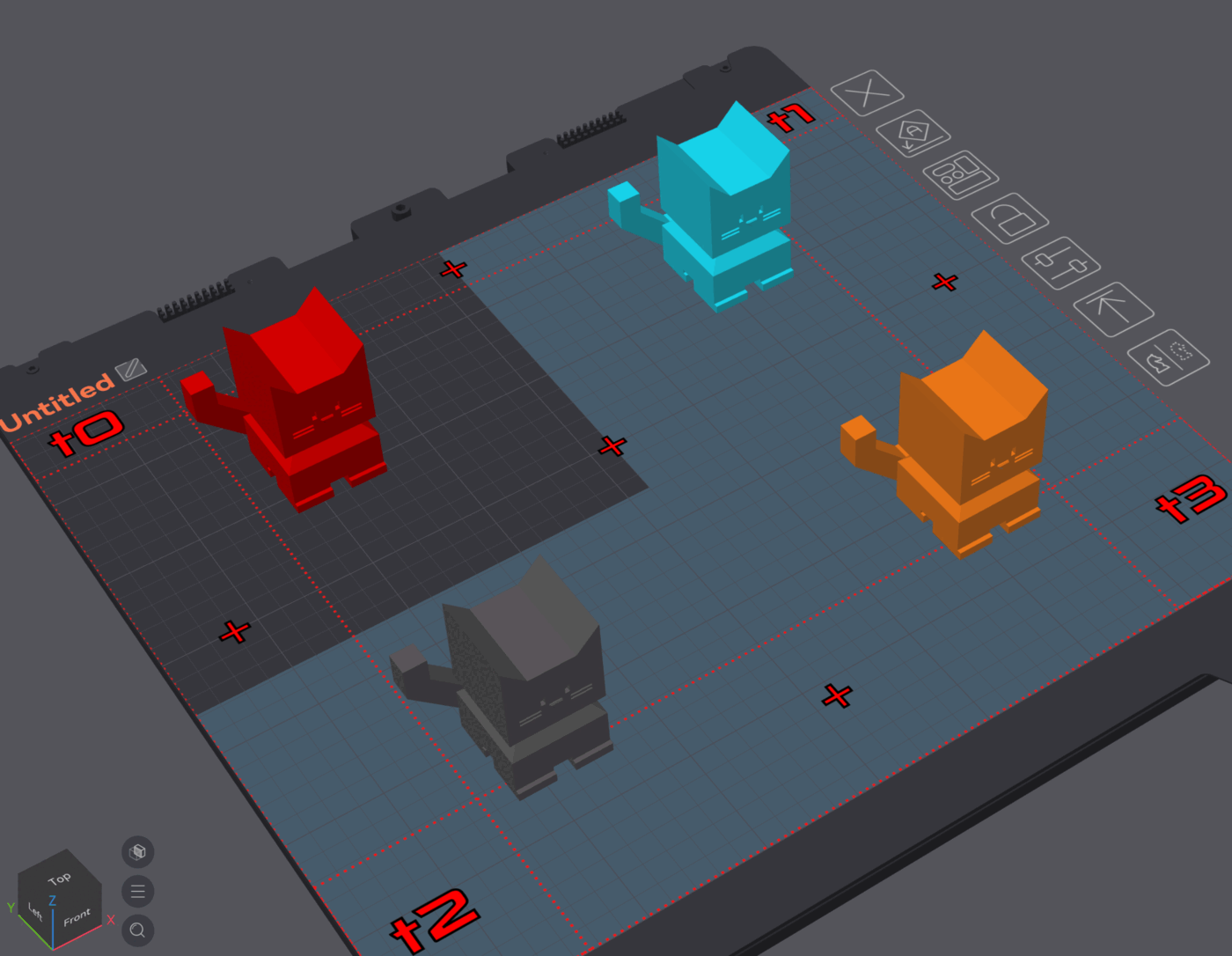
Each carriage prints with the filament on its own toolhead. If an MMU or AFC feeds a toolhead with several filaments, click its ghost to choose which of them that carriage prints with. The choice is saved with the plate.
Multi-color printing
In a copy or mirror mode, a plate normally uses a single filament, since the other carriages can only repeat T0's moves. The exception is a dual-gantry printer with two or more carriages per gantry: giving a tool on T0's gantry the Span role lets it and T0 print a part in several colors, while the other gantry copies or mirrors it.
Each color must be on T0 or a Span partner, one toolhead each. Two filaments on the same toolhead, such as two lanes of an MMU, cannot be combined in a parallel mode, because the other carriages cannot follow a filament swap. Filament changes added from the layer slider count as colors too.
Mixed filaments, which blend several filaments in alternating sub-layers, cannot be used in a parallel mode at all. Switch the plate to Primary to print them.
Temperatures and pressure advance
In a parallel mode, each active carriage gets its own filament's pressure advance at the start of the print, and its own temperature from the second layer on. Heat the other carriages for the first layer in your machine start G-code: is_extruder_used is true for every active carriage's filament, so a start G-code that heats each used extruder covers them.
Pressure advance is written in the form your firmware expects:
| Firmware | Command |
|---|---|
| Klipper | SET_PRESSURE_ADVANCE ADVANCE=... EXTRUDER=extruder1 (extruder for T0) |
| RepRapFirmware | M572 D1 S... |
| Marlin 2 | M900 K... T1 |
The toolhead number goes into the command unchanged, so the firmware has to number its extruders the same way: [extruder1] in Klipper, extruder drive 1 in RepRapFirmware. Marlin keeps a separate value for each extruder only when it is built with DISTINCT_E_FACTORS; without it, every carriage, T0 included, ends up with the value written last.
Other firmware flavors get a single pressure advance command without a toolhead number. Adaptive pressure advance adjusts only the tool printing the sliced toolpaths, T0 or its Span partner (always drive 0 on RepRapFirmware); the other carriages keep their starting value. In Primary mode, temperatures and pressure advance work as on any other printer.
Preview
The preview animates every active carriage along with T0 and draws a box around each toolhead, sized from the nozzle clearances, so you can check that they stay apart. Boxes are drawn only when both nozzle clearances are above zero. With a Span partner, T0's gantry shows one box on whichever of the two is printing, the other gantry gets one box when both of its carriages have the same role, and with Firmware-managed zones enabled no boxes are drawn. Turn the boxes off with View → Show IDEX/IQEX Toolhead if they hide the toolpaths.
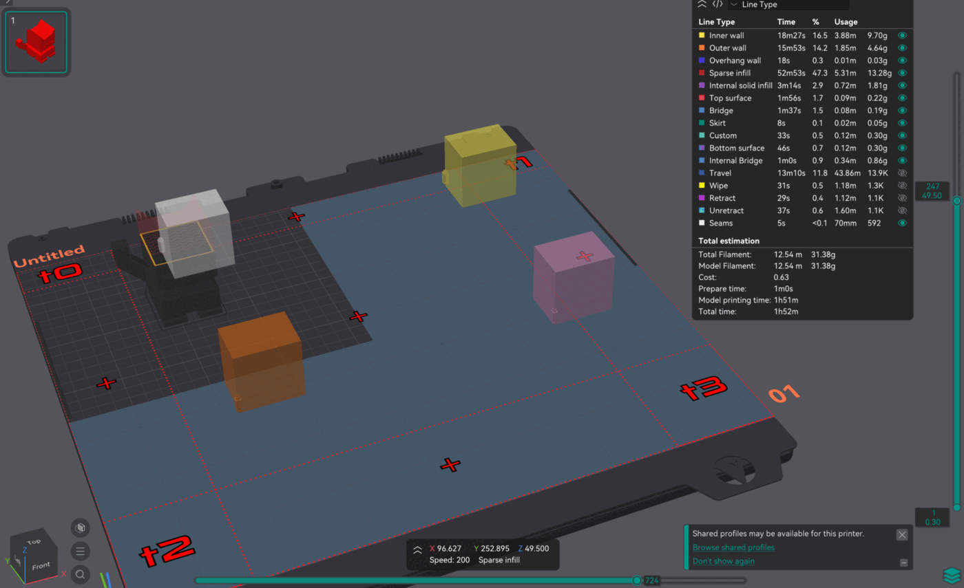
Only the sliced toolpaths are drawn: T0's, plus its Span partner's. The other carriages' paths are not.
Checks before slicing
Some problems stop the plate from slicing, with a message that explains the problem:
- A part or the prime tower outside the primary zone or inside a clearance strip.
- A plate using more than one filament in a mode that cannot print it. See Multi-color printing.
- A mixed filament in a parallel mode.
- None of the plate's filaments loaded on T0, the tool that prints the sliced part.
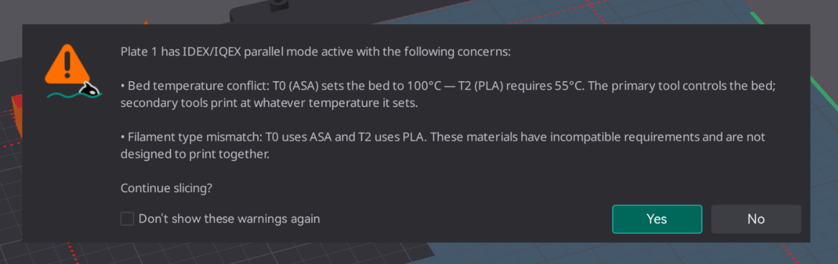
Slice plate and Slice all also show a warning, which you can accept or cancel, when another active carriage's filament has a different filament type or a bed temperature more than 5 °C away from T0's. T0 controls the bed temperature, so the other carriages print at whatever it sets. The warning can be turned off from its dialog and turned back on with Pre-slice warnings.
Limitations
- Toolpaths are not checked for collisions layer by layer. The placement check keeps parts out of the clearance strips but does not check each layer's moves. Leave room at the zone edges.
- Brims and skirts are not checked against the zones or the clearance strips. Leave room for them between parts and the zone edges.
- Per-extruder printable areas are not combined with the zones. A part is checked against the primary zone only.
- Deleting a mode switches the open plates that use it to Primary. Plates that name a mode the printer no longer has, after a rename or in a saved project, print in Primary with a warning when slicing.
- All carriages print the same part. Carriages cannot print different objects in the same mode.