Top and Bottom Shells
Controls how the top and bottom solid layers (shells) are generated.
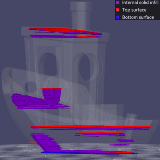
- Shell Layers
- Shell Thickness
- Surface Density
- Infill/Wall Overlap
- Surface Pattern
- Surface Expansion
- Center Surface Pattern On
- Fill Order
Shell Layers
Variables: top_shell_layers, bottom_shell_layers.
Type: Integer.
CLI Example: --top-shell-layers=1 (same pattern for the other variables above).
This is the number of solid shell layers, including the surface layer.
When the thickness calculated from this value is less than shell thickness, the shell layers will be increased.
These layers are printed over the sparse infill, so increasing shell layers will increase overall part strength and top surface quality. It's usually recommended to have at least 3 shell layers for most prints.
Shell Thickness
Variables: top_shell_thickness, bottom_shell_thickness.
Type: Float.
CLI Example: --top-shell-thickness=1 (same pattern for the other variables above).
The number of solid layers is increased during slicing if the thickness calculated from shell layers is thinner than this value. This avoids having too thin a shell when layer height is small.
0 means this setting is disabled and shell thickness is determined entirely by shell layers.
Surface Density
Variables: top_surface_density, bottom_surface_density.
Type: Percentage.
CLI Example: --top-surface-density=20% (same pattern for the other variables above).
This setting controls the density of the top and bottom surfaces. A value of 100% means a solid surface, while lower values create a sparse surface.
This can be used for aesthetic purposes, improving grip or creating interfaces.
Infill/Wall Overlap
Mode: Advanced.
Variable: top_bottom_infill_wall_overlap.
Type: Percentage.
CLI Example: --top-bottom-infill-wall-overlap=20%.
The top solid infill area is slightly enlarged to overlap with walls for better bonding and to minimize pinholes where the infill meets the walls.
A value of 25-30% is a good starting point. The percentage value is relative to the line width of the sparse infill.
Tip
Check Monotonic Line to learn about its overlaying differences with Monotonic and Rectilinear.
Surface Pattern
Variables: top_surface_pattern, bottom_surface_pattern.
Type: Choice.
Options: monotonic, monotonicline, rectilinear, alignedrectilinear, concentric, spiralinset, hilbertcurve, archimedeanchords, octagramspiral.
CLI Example: --top-surface-pattern=monotonic (same pattern for the other variables above).
This setting controls the pattern of the surfaces.
If Shell Layers is greater than 1, the surface pattern will be applied to the outermost shell layer only and the rest will use Internal Solid Infill Pattern.
Tip
See Infill Patterns Wiki List with detailed specifications, including their strengths and weaknesses.
The surface patterns are:
- Concentric
- Rectilinear
- Monotonic
- Monotonic Line Usually Recommended for Top.
- Aligned Rectilinear
- Hilbert Curve
- Archimedean Chords
- Octagram Spiral
Tip
Enable Align directions to model to make the top/bottom surface fill direction follow the model's orientation on the build plate.
Surface Expansion
Mode: Advanced.
Variable: top_surface_expansion.
Type: Float.
CLI Example: --top-surface-expansion=1.
Important
NEW FEATURE: Top surface expansion (expansion, margin and direction)
Available in: Nightly builds or Releases greater than 2.4.2.
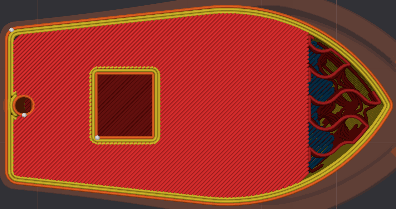
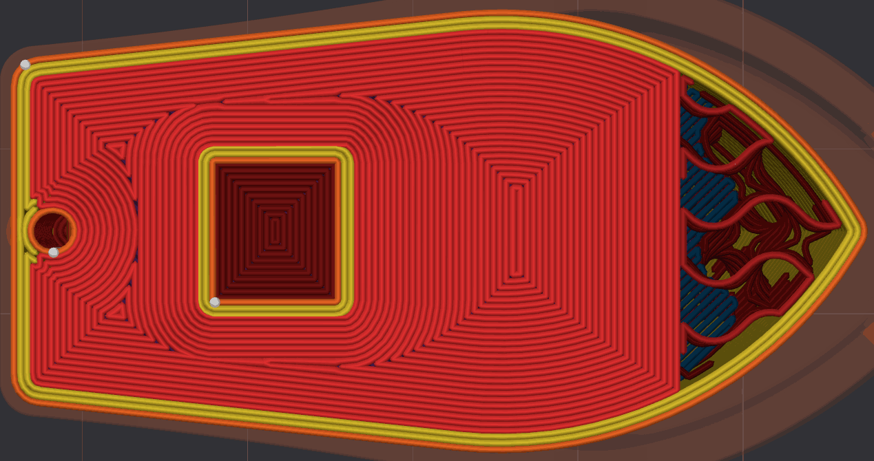
Expands the top surfaces by this distance (in mm) to connect distinct top surfaces and fill the gaps left where a feature rises through them.
This is useful when the top surface is interrupted by a raised feature, such as text or a boss on a plane, or when overlapping objects would otherwise split it: expanding the surface removes the holes beneath these features, keeps the top-surface pattern uninterrupted, and anchors the solid infill for a cleaner finish when printing on top. It also improves concentric top surfaces, whose pattern would otherwise be broken up by those small holes.
The expansion is applied to the original top surface, before any other processing such as bridging or overhang detection. Set to 0 to disable it.
- Original
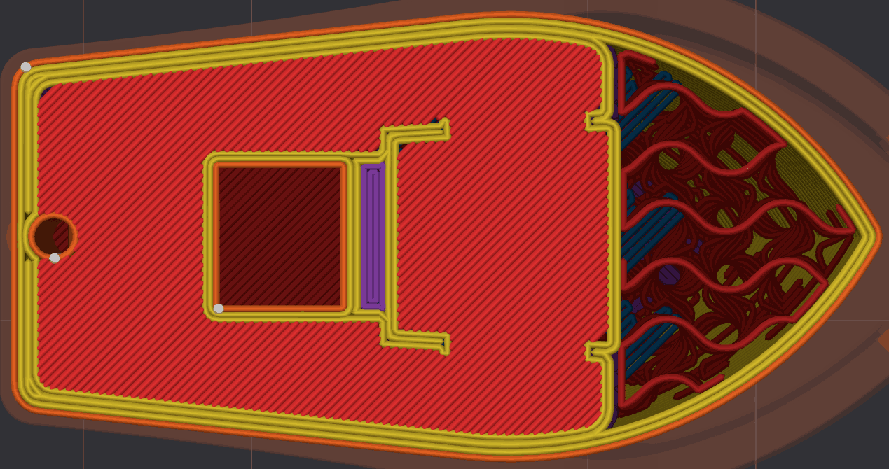
- Expanded by 5 mm
- Improved concentric top surface.
- Before:
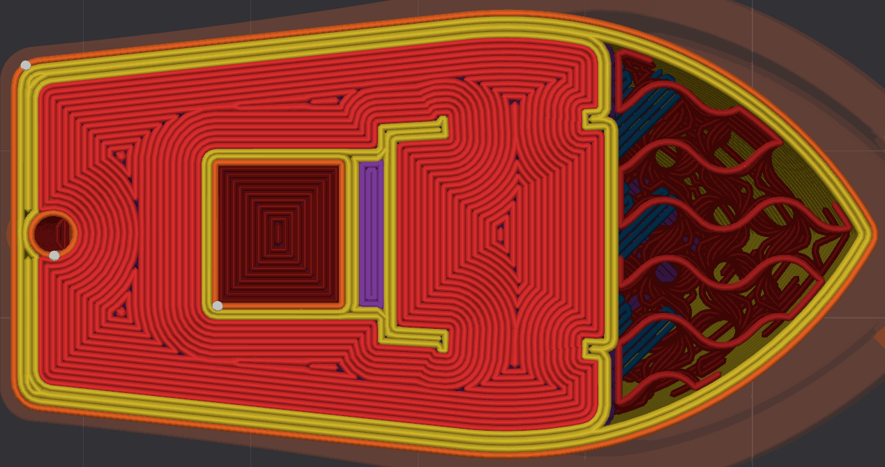
- After:
- Before:
Note
Surface expansion needs a top solid surface to grow. It does nothing when Shell Layers is 0 (the top surfaces are then treated as internal) or when Surface Density is 0% (the top surface is left unfilled).
Surface Expansion Margin
Mode: Advanced.
Variable: top_surface_expansion_margin.
Type: Float.
CLI Example: --top-surface-expansion-margin=1.
Using Surface Expansion may cause a surface that did not previously touch the model's outer walls to now reach them, which can create contraction marks (such as a hull line) on the outer walls.
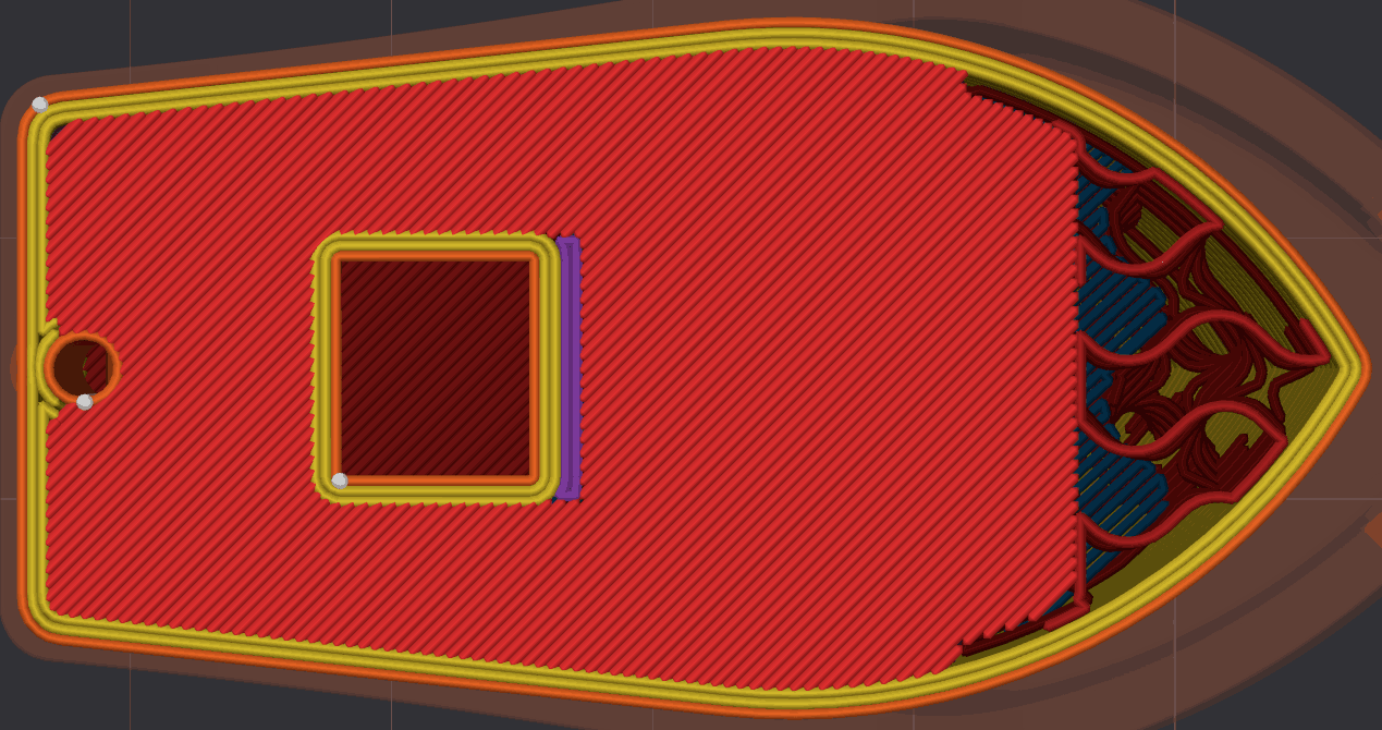
Adding a margin (in mm) keeps the expansion away from the walls where possible, so no hull line is created. The example below uses a 5 mm expansion with a 2 mm margin — compare it with the 5 mm expansion above, which reaches the walls.
The margin is the real clearance left between the expanded top surface and the walls, so it is measured from the band the walls occupy. When Only one wall on top surfaces is enabled, that band is a single wall, since that is all that remains over a top surface.
Surface Expansion Direction
Mode: Advanced.
Variable: top_surface_expansion_direction.
Type: Choice.
Options: inward_and_outward, inward, outward.
CLI Example: --top-surface-expansion-direction=inward_and_outward.
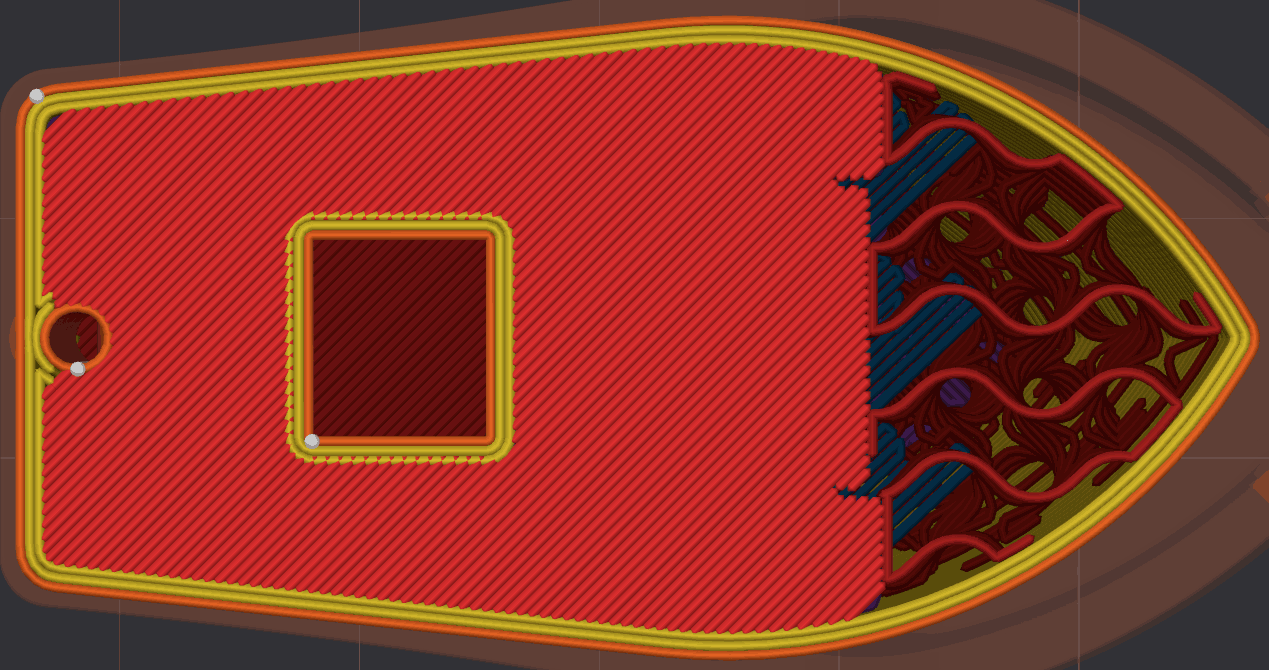
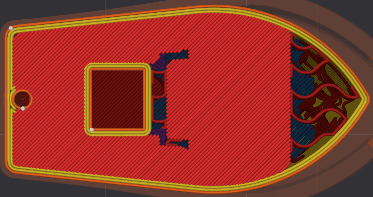
Direction in which the Surface Expansion grows:
- Inward: grows into the holes and gaps left by features rising from the middle of a top surface.
- Outward: grows the outer edge of the surface, connecting surfaces separated by features that can divide a surface, such as a lattice pattern.
- Inward and Outward: does both. This is the default.
Surface Expansion and Only One Wall
Only one wall on top surfaces keeps a single wall where a top surface is detected. With more than one wall loop, the remaining inner walls used to be rerouted around the top surface, which could ring a feature with walls that were not needed, and cut up — or overlap with — an expanded top surface.
When Surface Expansion is in use, those inner walls are removed over the top surface instead, so the expanded surface stays continuous and the pattern is not interrupted:
- Classic wall generator: the inner walls running over the top are dropped whole. The space they leave is taken by the expanded top surface, and whatever it does not cover becomes internal solid infill.
- Arachne wall generator: the inner walls are cut instead of dropped, so only the part running over the top surface is removed and the rest is kept where the geometry continues upward.
Note
This behavior needs a top fill that can actually take that space. With Surface Expansion at 0 or Surface Density at 0%, the inner walls are generated as before, preserving the internal support.
Center Surface Pattern On
Mode: Expert.
Variable: center_of_surface_pattern.
Type: Choice.
Options: each_surface, each_model, each_assembly.
CLI Example: --center-of-surface-pattern=each_surface.
Important
NEW FEATURE: Center surface pattern on
Available in: Nightly builds or Releases greater than 2.4.2.
Chooses where the centering point of centered top/bottom surface patterns (Archimedean Chords, Octagram Spiral) is placed.
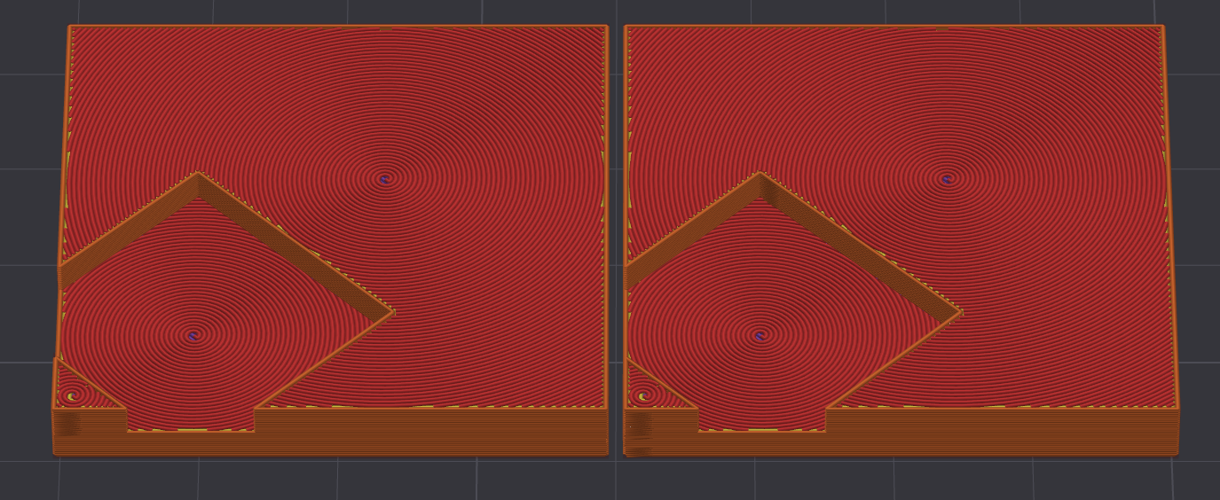
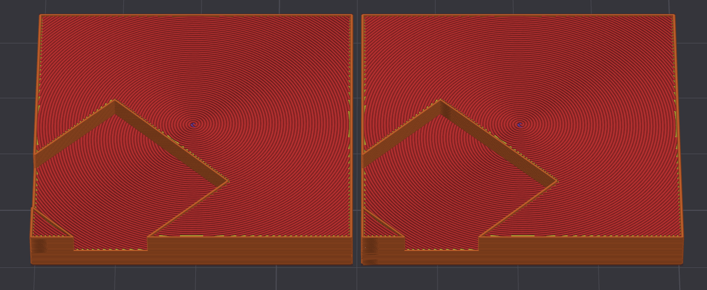
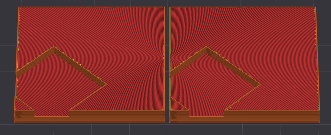
By default these patterns are centered individually on each surface, which does not keep the pattern continuous across a whole product — a drawback for some artistic prints where the surfaces should read as one piece. This setting widens the scope of the shared center:
- Each Surface: centers the pattern on every individual surface region, so each island is symmetric on its own. This is the previous behavior.
- Each Model: combines all the surfaces of one model — or each shape in the assembly — under a single center. Parts that touch or overlap share one center; parts detached from the rest each get their own.
- Each Assembly: all the surfaces of the assembly fall under a single shared center. Well suited for articulated models that should keep one continuous pattern across their parts.
Fill Order
Mode: Advanced.
Variables: top_surface_fill_order, bottom_surface_fill_order.
Type: Choice.
Options: default, outward, inward.
CLI Example: --top-surface-fill-order=default (same pattern for the other variables above).
Important
NEW FEATURE: Fill order
Available in: Nightly builds or Releases greater than 2.4.2.
Direction in which the top and bottom surfaces are filled when using a center-based pattern (Concentric, Archimedean Chords, Octagram Spiral). The spirals/rings are then deposited consistently inward or outward instead of following the default shortest path.
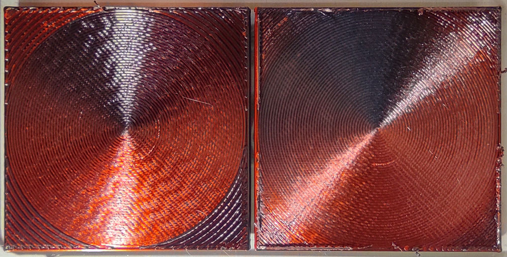
- Default: uses legacy ordering.
- Outward: starts at the center of the surface, so any excess material is pushed towards the edge where it is least visible. Preferred for top surfaces, as it hides small imperfections better.
- Inward: starts at the edge and ends with the tight curves at the center. Preferred for bottom surfaces, as starting each surface with the wider outer curves improves first layer adhesion on build plates where the tight curves at the center may not stick.